


Surface Roughness Chart: A Comprehensive Conversion and Process Comparison Guide for Ra, Rz, and RMS
Excerpt:
Surface roughness is a symbol found in the lower-right corner of every drawing—Ra 0.8, Ra 3.2, ▽▽▽… But behind the same set of numbers, different machining processes can result in a difference of an order of magnitude. This article clearly explains the definitions of surface roughness parameters, conversion relationships, grade comparison tables, and process ranges all at once. In particular, it explains why the as-cast surface of die-cast parts can be used directly without secondary machining, helping you avoid making guesses during design, quoting, and acceptance.
Article Catalog[Hidden]
- 1. What Is Surface Roughness?
- 2. Four Core Parameters: Ra / Rz / Rq / Rt
- 3. Comprehensive Comparison Table of Surface Roughness Grades
- 4. Roughness Ranges for Common Machining Processes
- 5. How is surface roughness measured?
- 6. How to Select a Surface Roughness Grade Based on Application
- 7. Frequently Asked Questions
1. What Is Surface Roughness?
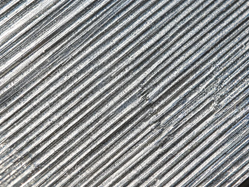
When the machined parts are examined under a microscope, their seemingly smooth surfaces are actually covered withPeaks and valleys left by cutting tools, molds, or abrasive particles. Surface roughness refers to the degree of variation in the microscopic geometric topography between adjacent peaks and valleys—it is a quantitative measure of "surface finish."
In engineering, surface roughness directly determines theFitting accuracy, friction and wear, sealing performance, corrosion resistance, and fatigue life: If the surface roughness is too high, sealing surfaces will leak and mating surfaces will suffer premature wear; if the surface roughness is too low, machining costs will skyrocket. Therefore, understanding surface roughness charts and selecting the appropriate roughness grade are fundamental skills for every design and manufacturing engineer.
2. Four Core Parameters: Ra / Rz / Rq / Rt
When the same surface is "calculated" using different mathematical methods, different numerical values are obtained. The four most common parameters on engineering drawings are as follows:
| parameters | Chinese Name | Calculation Method | Most Common Scenarios |
|---|---|---|---|
| Ra | Arithmetic Mean Deviation of Contours | The average of the absolute values of the deviations from the centerline within the sampling length | The vast majority of machined parts and drawings include default dimensions. |
| Rz | Average Maximum Height (10-Point Average Height) | The average of the five greatest "peak-to-trough" heights | Sealing surfaces, fatigue-critical components |
| Rq (RMS) | Root Mean Square Error | The square root of the average of the squares of the deviations | Optical Surfaces, Research Scenarios |
| Rt | Maximum Height of Outline | Calculate the total elevation difference between the highest peak and the lowest valley within the specified length | Focus on extreme defects and spikes |
The conversion relationships among the three parameters can be summarized as follows: For a typical machined surface,RMS is approximately equal to Ra × 1.11; whereas Rz is approximately four times Ra(Empirical approximation). In other words, if a drawing specifies Ra 0.8 μm, the corresponding Rz value is approximately 3.2 μm.
Important Information for Engineers:Ra is calculated as the average of the entire contour; a deep scratch or a high peak will be "diluted" by a large number of normal areas. Therefore, for surfaces such as sealing surfaces, cylinder bores, and bearing seats, which are sensitive toSensitivity to Defects at the Deepest LevelFor these parts, it is not sufficient to consider only Ra; Rz or Rt should also be specified.
3. Comprehensive Comparison Table of Surface Roughness Grades
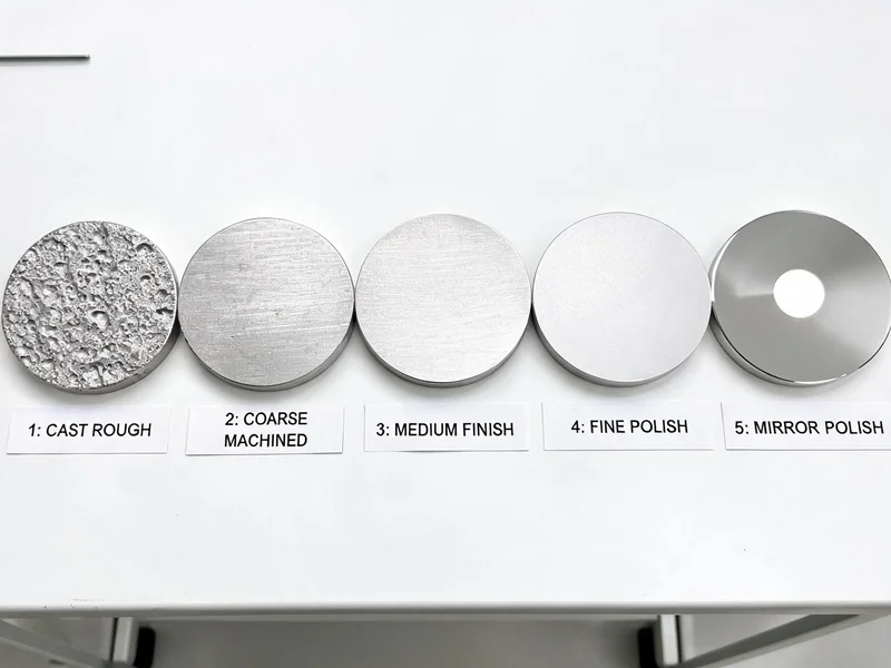
Internationally, the term N Levels (N1–N12, based on ISO 1302) Here is the classification, with each grade corresponding to a standard Ra value. Below is the complete Ra (micrometers/micron-inches) conversion table:
| N Level | Ra (μm) | Ra (μin) | Typical Techniques/Appearance |
|---|---|---|---|
| N2 | 0.05 | 2 | Mirror Polishing |
| N3 | 0.1 | 4 | Honing, Grinding |
| N4 | 0.2 | 8 | Fine Grinding |
| N5 | 0.4 | 16 | hardened |
| N6 | 0.8 | 32 | Precision Turning, Precision Grinding |
| N7 | 1.6 | 63 | Finishing |
| N8 | 3.2 | 125 | General Machining |
| N9 | 6.3 | 250 | Rough Machining |
| N10 | 12.5 | 500 | Rough turning and milling, waterjet cutting |
| N11 | 25 | 1000 | Rough surface |
| N12 | 50 | 2000 | As-cast blanks, black scale |
In the table above,Ra 0.8 μm (N6) and Ra 3.2 μm (N8) These are the two most common thresholds: the former marks the starting point for "finishing," while the latter is the default requirement for the vast majority of functional parts. 1 μm is equivalent to 39.37 micro-inches, so when you see "micro-inch" values such as 32, 63, or 125 on a drawing, they correspond to 0.8, 1.6, and 3.2 micrometers, respectively.
4. Roughness Ranges for Common Machining Processes
Different processes have inherently different limits on the surface roughness they can achieve, and this is one of the most common sources of disagreement between design and manufacturing. The table below shows the typical surface roughness ranges for each process:
| Processing | Typical Ra (μm) | Maximum Attainable Ra (μm) | instructions |
|---|---|---|---|
| Die Casting (as-cast) | 0.8 ~ 3.2 | 0.8 | Metal die casting, with a fine-grained surface as-cast |
| sand casting | 6.3 ~ 25 | 12.5 | A grain-like pattern is imprinted on the casting |
| Precision Casting (Investment Casting) | 1.6 ~ 6.3 | 0.8 | Near-net-shape forming often eliminates the need for finishing |
| Hot-rolled / Forged | 3.2 ~ 12.5 | 1.6 | Scale and Rolling Marks |
| Waterjet Cutting | 3.2 ~ 12.5 | 1.6 | Fine sand produces a smoother finish when fed slowly. |
| drilled hole | 3.2 ~ 6.3 | 1.6 | Fluted Drill Bits + Coolant = A Smoother Finish |
| mill | 0.8 ~ 6.3 | 0.4 | Precision milling up to N5 |
| Precision Turning | 0.8 ~ 1.6 | 0.4 | - |
| hardened | 0.4 | 0.1 | - |
| Grinding / Honing | 0.1 | 0.05 | Mirror-grade |
The practical significance of this table is that if you are looking for a batch of housings or brackets,Die casting Capable of producing as-cast surfaces with a Ra of 0.8–3.2 μm, with many non-sealing surfacesNo need for secondary machining on a machine tool; whereas the same sizesand castingThe only results obtained were Ra values between 6.3 and 25 μm, which almost certainly require leaving a machining allowance for subsequent finishing. This is precisely why thin-walled parts produced in large volumes are commonly selected Die casting One of the key reasons for this, as opposed to sand casting.
For die-cast parts already in use, key locations such as mating surfaces, reference surfaces, and threaded holes still require CNC Machining To ensure accuracy and surface finish of Ra 0.8 μm or less—which is the standard practice for the "die-casting plus finishing" combination in the automotive and electronics industries. The surface quality of the mold cavity itself directly determines the baseline surface roughness of the casting; therefore, Mold Manufacturing The effort put into polishing and grinding at each stage will ultimately be reflected in the surface of the finished product.
5. How is surface roughness measured?
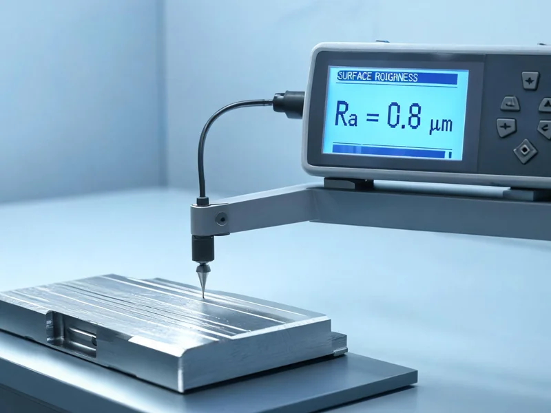
The most common method for measuring surface roughness isStylus-Type Profiler (Surface Roughness Tester). The principle is quite intuitive: an extremely fine diamond stylus slowly glides across the surface being measured, converting the peaks and valleys into electrical signals via a sensor, which are then GAUSS FilterRemove macro-scale ripples, and finally calculate parameters such as Ra, Rz, and Rq within the sampling length.
Two points that are easily overlooked during measurement: First,Sampling LengthFirst, the evaluation length must be selected correctly; generally, a longer sampling length (such as 2.5 mm) is used for rough surfaces, while a shorter one (such as 0.25 mm) is used for fine surfaces. Second, the measurement direction shouldPerpendicular to the machining pattern(turning marks, milling marks); otherwise, the measured values will be significantly lower than actual. For complex internal cavities in castings that cannot be directly accessed by a probe, a visual comparison can be made using a surface roughness reference template.
6. How to Select a Surface Roughness Grade Based on Application
The essence of selecting a surface roughness grade is to strike a balance between "functional requirements" and "machining costs." For every one N-grade increase in surface roughness (halving the Ra value), machining time and costs typically rise by 30% to 60%. Here are a few practical recommendations based on intended use:
- Non-mating, non-sealed exposed surfaces: Ra 3.2–6.3 μm (N8–N9) is sufficient; die-cast as-cast parts that have undergone rough turning meet this requirement.
- General mating surfaces, locating surfaces: Ra 1.6–3.2 μm (N7–N8), finish turning or finish milling.
- Sliding Fit, Bearing Seat: Ra 0.4–0.8 μm (N5–N6); requires precision grinding.
- Sealing surfaces, cylinder bores: Ra 0.2–0.4 μm (N4–N5), while simultaneously controlling Rz to prevent air leaks caused by isolated deep scratches.
- Fatigue-critical components, mirror surfaces: Ra ≤ 0.1 μm (N3 or higher), honing or lapping.
Reminder from Industry Professionals:The failure of many parts is not due to insufficient overall surface roughness, but ratherLocal Defects—A porosity, a pit caused by trapped gas, or burrs and flash. For die-cast parts used in applications requiring airtightness or subject to fatigue, in addition to examining the Ra value, attention must also be paid to internal density. For information on the causes of related defects and corresponding countermeasures, please refer to Aluminum die casting defects and their causes An article.
7. Frequently Asked Questions
Q1: What does surface roughness Ra mean?
Ra is the arithmetic mean deviation of the profile; it refers to the arithmetic mean of the absolute values of the deviations of each point on the surface profile from the centerline over the sampling length, and is the most commonly used roughness parameter.
Q2: How do you convert between Ra and Rz?
As a rule of thumb, Rz is approximately four times Ra, i.e., Rz ≈ 4 × Ra. For example, an Ra value of 0.8 μm corresponds to an Rz value of approximately 3.2 μm. For an accurate conversion, the specific machining method must be taken into account.
Q3: What is the typical surface roughness of die-cast parts?
The as-cast surface finish of die-cast parts is typically Ra 0.8–3.2 μm, which is significantly better than that of sand-cast parts (Ra 6.3–25 μm); many non-sealing surfaces can be used directly without secondary machining.
Q4: What instrument is used to measure surface roughness?
The most commonly used stylus-type profilometer involves sliding a probe along the surface and calculating parameters such as Ra and Rz after filtering; complex internal cavities can be visually inspected using a reference template.
Q5: What is the difference between Ra and RMS?
Ra is the arithmetic mean of absolute values, and RMS (i.e., Rq) is the root mean square. For typical machined surfaces, RMS ≈ Ra × 1.11; RMS is more sensitive to peaks.