


What is precision machining for 3D-printed molds?
Excerpt:
"The phrase "3D-printed molds" can easily lead people to believe that once printing is complete, the parts are ready for immediate production. However, actual industry practice is quite the opposite: virtually none of the inserts and cores produced through metal additive manufacturing are delivered without undergoing precision machining. So-called "precision machining for 3D-printed molds" simply refers to the use of subtractive methods—such as CNC milling, grinding, electrical discharge machining (EDM), and polishing—to refine printed parts from "raw material grade" to "mold grade.” This article thoroughly explains the principles behind this process, why it is necessary, which surfaces require machining, and the required tolerance levels.
Article Catalog[Hidden]
- 1. Concept: Hybrid Manufacturing—The Division of Labor Between Additive and Subtractive Manufacturing
- 2. Why Must 3D-Printed Molds Be Precision-Machined?
- 3. Critical surfaces requiring precision machining
- 4. Key Metrics: Tolerances and Surface Roughness
- 5. Overview of Common Post-Processing Techniques
- 6. Material Selection: H13 / 420 / Copper
- 7. Why Are Contour-Cooling Molds More Dependent on Precision Machining?
- 8. How to Choose a Service Provider
- 9. Frequently Asked Questions
1. Concept: Hybrid Manufacturing—The Division of Labor Between Additive and Subtractive Manufacturing
Precision machining for 3D-printed molds; the technical term for this is Hybrid Manufacturing —Integrating additive manufacturing (i.e., metal 3D printing/Selective Laser Melting, SLM) with subtractive manufacturing (CNC milling, grinding) into a single process.
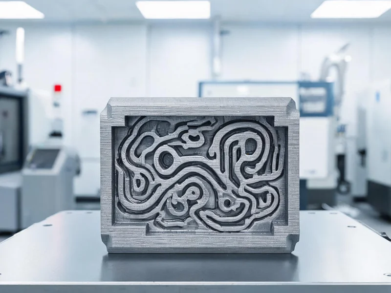
The division of labor between the two is very clear: 3D Printing Is Responsible for "Shape" ...it can achieve what traditional drilling simply cannot. Conformal Cooling Channels , one-step molding of embedded flow channels and irregular cavities; Precision Machining Ensures "Accuracy" ...It ensures that the parting lines, locating holes, and sealing grooves—the surfaces that truly determine whether a mold is usable—meet the tolerances and surface finishes specified in the drawings. In short: additive manufacturing offers freedom, while subtractive manufacturing delivers precision.
The most common process route is"Printing—Post-Processing": First, print a near-net-shape insert with some allowance, then use a CNC machine to finish the critical surfaces to specification. This two-step process is already widely used in injection molds, Die casting high-value-added molds, such as injection molds and blow molds.
2. Why Must 3D-Printed Molds Be Precision-Machined?
Many people who are new to additive manufacturing ask: Isn’t 3D printing supposed to be "net shaping"? The answer is—metal 3D printing is "near-net shaping," not "net shaping." Parts produced via 3D printing have three inherent defects that prevent them from being used directly as molds:
- Layer roughness:SLM is produced by melting and depositing metal powder layer by layer, resulting in a surface with a natural stepped pattern; the as-cast surface roughness is typically Ra 12.5 µm Around that level, which falls far short of the Ra 0.8 µm required for the mold cavity.
- Insufficient positioning accuracy:Printing accuracy is generally within ±0.05 to 0.1 mm, whereas the parting lines and locating pin holes of molds often require tolerances within ±0.01 mm.
- Micropores and Residual Stress:The printing process may leave behind microporosity and internal stresses, which require HIP (hot isostatic pressing), heat treatment, and subsequent machining to eliminate or mitigate.
Therefore, the true value proposition of "3D-printed molds" is not that they eliminate the need for machining, but rather Build a competitive edge in complex cooling and lightweight structures—areas where traditional manufacturing falls short—and then use precision machining to address any shortcomings in accuracy. . Only when you understand this can you truly understand this craft.
3. Critical surfaces requiring precision machining
Not every surface of a printed part requires precision machining. The surfaces that truly require CNC machining or grinding are those that "rely on contact and fit to ensure functionality":
| Surface Type | corresponds English -ity, -ism, -ization | Typical Requirements |
|---|---|---|
| Parting Line / Molding Surface | Factors Affecting Molding Precision and Flash | High flatness, Ra ≤ 0.8 µm |
| Locating Holes / Guide Post Holes | Alignment of Upper and Lower Dies | ±0.005–0.01 mm |
| Cavity / Core Molding Surface | Determines the product's appearance and demolding | Ra 0.2–0.8 µm (polished) |
| Seal Groove / Sealing Surface | Cooling Water and Oil Line Seals | Ra ≤ 0.8 µm; must be airtight |
| Threaded / Fastener Holes | Compatibility with Standard Parts | Standard Thread Precision |
| Reference Surface / Clamping Surface | Positioning Reference for Subsequent Processes | Flatness, Parallelism |
Reminder from Industry Professionals: It is crucial to allow for a sufficient finishing allowance when designing 3D-printed parts. If the allowance is too large, the benefits of 3D printing are negated; if it is too small, surface defects cannot be properly repaired. Generally, a finishing allowance of 0.3 to 0.5 mm is recommended for critical surfaces, though the specific value depends on the 3D printer and subsequent processing steps.
4. Key Metrics: Tolerances and Surface Roughness
The extent to which precision machining can "improve" is clearly illustrated by two figures. The table below compares the performance gap between additive manufacturing and precision machining:
| norm | Metal 3D Printing (As-Printed) | After CNC precision machining |
|---|---|---|
| Positioning/Dimensional Accuracy | ±0.05 to 0.1 mm | ±0.005 to 0.01 mm |
| Surface roughness Ra | ≈ 12.5 µm | Precision Milling: 1.6 µm / Grinding: 0.4 µm / Mirror Finish: 0.2 µm |
| Suitable Occasions | Non-critical rough surfaces | Parting line, guide, seal, molding surface |
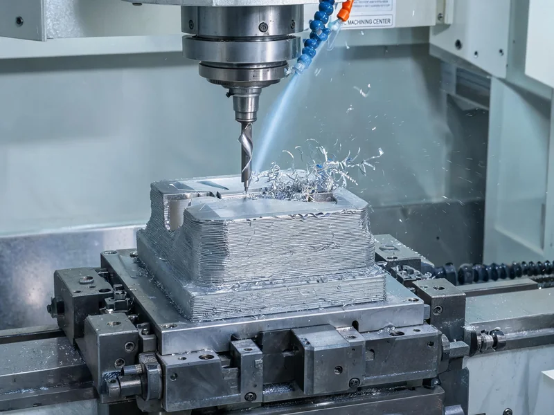
To achieve a surface roughness of Ra 0.2 µm from an initial Ra 12.5 µm, several processing steps are typically required: rough milling to remove excess material → fine milling to Ra 1.6 µm → grinding to Ra 0.4 µm → polishing to a mirror finish with Ra 0.2 µm. As the surface roughness decreases by one grade, the labor hours required increase significantly, so Focus your efforts only on the surfaces that truly require a smooth finish ... is a key strategy for controlling costs.
5. Overview of Common Post-Processing Techniques
Precision machining of 3D-printed molds is not a single process, but rather an entire "post-processing chain." Common steps include:
- CNC Milling / Turning:The primary sources of precision are the machining of parting lines, holes, slots, threads, and end faces.
- Grinding:Used for flatness, parallelism, and precision surfaces with a surface roughness of Ra 0.4 µm or less.
- EDM (Electric Discharge Machining):Machining deep, narrow grooves, sharp corners, and local shaping of hard materials—particularly useful after the printed part has been quenched.
- Grinding / Polishing:Achieve a mirror-like finish with a surface roughness of Ra 0.2 µm on the molded surface to improve demolding and product surface quality.
- Sandblasting / Shot Blasting:Unify the surface texture of non-critical surfaces and remove slag.
- HIP (Hot Isostatic Pressing):Seal internal microporosity to improve density and fatigue performance.
- Heat Treatment:H13 is typically quenched at 860°C and then double-tempered at 520°C to achieve a hardness of 48–56 HRC.
A reliable supplier will organize these processes into a clear production sequence based on the functional requirements of the parts, rather than just "printing them and then milling them haphazardly."
6. Material Selection: H13 / 420 / Copper
The selection of materials for 3D-printed mold inserts essentially follows the same principles as those used for traditional mold steel, except that the material is now in powder form:
| makings | Hardness (after heat treatment) | Applicable Scenarios |
|---|---|---|
| H13 Hot-Work Tool Steel | 48–56 HRC | Industry standards for die-casting and injection-molding tools; resistance to thermal fatigue and thermal cracking |
| 420 Stainless Steel | Approx. 48–52 HRC | Corrosion-resistant molds for the medical and food industries, among others |
| C18150 Copper Alloy | Lower (priority given to thermal conductivity) | Inserts with high cooling requirements and a thermal conductivity exceeding 300 W/m·K |
For high-temperature operations such as die casting,H13 is the preferred choice—Its 5% chromium-vanadium-molybdenum alloy design maintains toughness and resistance to thermal cracking even under repeated thermal cycling, which is precisely why it is widely and extensively used in large automotive die-casting molds (such as engine blocks and battery housings). For further details on the structural and cooling design considerations for die-casting molds, please refer to Aluminum Die-Casting Mold Design An article.
7. Why Are Contour-Cooling Molds More Dependent on Precision Machining?
Conformal cooling is the most successful application of 3D printing in the mold industry: cooling channels are no longer just straight holes, but rather Follow the contour of the cavity , maintaining an equal distance from the molding surface, thereby dissipating heat evenly. The benefits are very direct—molding cycles are typically shortened by 20% to 30%, and product warpage and dimensional variations are also reduced.
But conformal cooling, on the other hand, This has made precision machining more difficult: The water channel is very close to the mold cavity—as close as a few millimeters. When machining the parting line or the sealing groove, if you cut too deep, you will Break Through the Waterway ... the entire insert must be scrapped. Therefore, conformal cooling inserts place higher demands on machining allowances, toolpaths, and inspection: after machining, the cooling channels must also be Pressure Testing and Leak Testing, ensuring that the water channels do not leak under prolonged high pressure. In actual mass production, conformal cooling inserts are typically used in conjunction with Aluminum Casting Production Debug the process together and verify the cooling effectiveness and product consistency under actual production conditions.
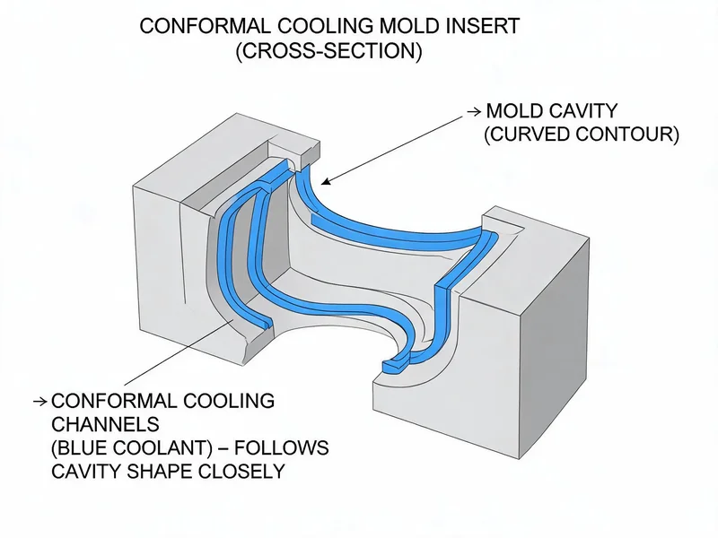
Key Risks: When designing conformal cooling inserts, it is essential to "consider machining during the design process." If cooling channels interfere with sealing grooves, ejector pin holes, or fastener holes, it is highly likely that holes will be damaged during machining. It is recommended to conduct a manufacturability review during the design phase to establish machining reference points and cooling channel clearances.
8. How to Choose a Service Provider
There are many factories that can print metal, but few can also handle the post-processing effectively. When selecting a supplier, we recommend focusing on the following four points:
- Is it an integrated "additive + subtractive" process?:It is best to have both printing and finishing done at the same facility to avoid buck-passing and repeated back-and-forth communication regarding allowances.
- Do you have experience in the mold industry?:Only a team with experience in die-casting and injection-molding tooling truly understands the logic behind machining parting lines, draft angles, and cooling channels.
- Is there a complete test report?Traceable data on tolerances, hardness, and surface roughness, as well as records of water channel pressure and leak tests.
- Heat Treatment and HIP Capabilities:It can achieve a hardness of 48–56 HRC and is capable of closing micro-pores during printing.
9. Frequently Asked Questions
Q1: What is precision machining for 3D-printed molds?
Performing post-processing such as CNC machining, grinding, EDM, and polishing on 3D-printed mold parts to achieve the required precision and surface finish on critical surfaces essentially constitutes hybrid manufacturing that combines additive and subtractive processes.
Q2: Why do 3D-printed molds still require CNC machining?
The printed parts have inherent surface texture (approximately Ra 12.5 µm) and microporosity, with a precision of only ±0.05 to 0.1 mm, which does not meet the fit and seal requirements for molds. They require secondary machining to achieve a precision of ±0.005 to 0.01 mm and a surface roughness of less than Ra 0.8 µm.
Q3: What materials are used for 3D-printed mold inserts?
H13 (48–56 HRC) is most commonly used for die casting and injection molding; 420 stainless steel is used for corrosion resistance; and C18150 copper is used in applications requiring high thermal conductivity.
Q4: What are the unique aspects of precision machining for conformal cooling molds?
Since the cooling channels are located close to the cavity, wall thickness must be controlled during machining to prevent the channels from being pierced; after machining, the cooling channels must also undergo pressure and leak tests.
Q5: Is precision machining of 3D-printed molds expensive?
Although the initial cost is higher than that of traditional cooling inserts, the investment can be quickly recouped by shortening cycle times (20%–30%) and reducing scrap caused by deformation, making it more cost-effective for high-volume production.