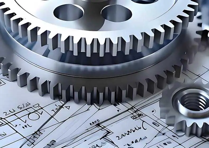
Ningbo Hexin Molding Co., Ltd. specializes in providing innovative solutions to customers through high-precision mapping and reverse design technology. Relying on advanced mapping equipment and professional software, the company accurately collects spatial data of objects and builds digital models to realize efficient reverse design in the fields of machinery manufacturing, industrial design, and building renovation. The team restores the details of product structure through refined mapping, optimizes the prototype with forward design thinking, helps customers to complete product iteration, process upgrading and technological transformation, and successfully delivers a number of complex projects in the scenarios of equipment manufacturing, cultural relics preservation, mold development, etc., which helps enterprises to reduce costs and increase efficiency with data-driven design.
Product Reverse Design
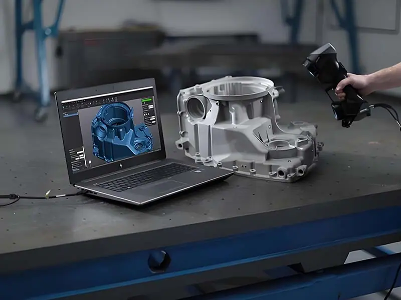
Ningbo Hexin Molding Co., Ltd.’s reverse engineering process is based on high-precision 3D laser scanning and UAV surveying technology. Through five core steps—[data acquisition, 3D scanning and modeling, feature analysis, CAD model reconstruction, and prototype optimization]—it accurately recreates digital models of complex components, industrial equipment, and architectural structures. By integrating forward-design thinking to optimize product performance and manufacturing processes, the company provides production-ready technical solutions for mechanical manufacturing, mold development, product comparison, and other fields. Through data-driven reverse engineering, it helps enterprises shorten R&D cycles, reduce modification costs, and enhance market competitiveness.
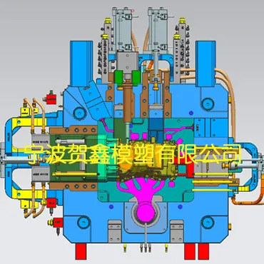
3D mold design uses digital technology to accurately build mold structure, covering die casting, low pressure and gravity casting three major processes, helping enterprises to efficiently produce high-precision parts. Die casting mold design is good at manufacturing complex parts (such as auto parts, electronic shell), relying on high-pressure high-speed filling technology, to ensure that thin-walled parts of the surface finish and dimensional precision, the core focus on the mold pressure strength and cooling efficiency; low-pressure mold design to fill the cavity with smooth low-pressure (0.01-0.05MPa) to reduce the defects of the air holes, adaptable to the aluminum alloy wheels and other high requirements of the densification of the large and medium-sized products, focusing on Optimization of pouring system and shrinkage channel; gravity mold design by virtue of the natural molding of metal weight, low cost, short cycle time, suitable for pipeline joints and other simple structure of the mass production, need to be targeted to solve the problem of insufficient filling and shrinkage. All three types of processes can be used to pre-judge defects through 3D modeling and simulation analysis (e.g., melt flow simulation, thermal stress detection), optimize parting surfaces and exhaust design, and reduce molding costs while improving yields, so as to meet the diversified demands for precision castings in automotive, aerospace, and home appliance industries.
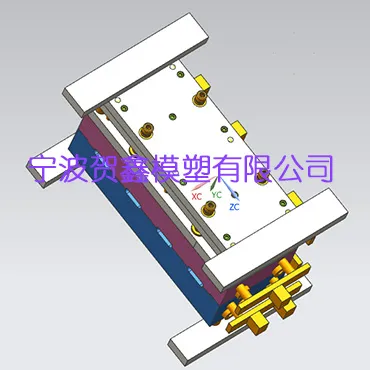
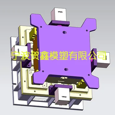
Die Casting Mold Design
Hersin uses advanced CAD/CAM software (e.g. SolidWorks, AutoCAD) to achieve high-precision digital development of molds and optimize runner systems, cooling structures and ejection solutions to improve mold life and productivity. Our design services cover automotive parts, electronic parts, household appliances and other die casting areas, through 3D simulation verification to reduce the cost of trial mold, to ensure the accuracy of the parting surface and tolerance ± 0.01mm control, to support the design of complex curved surfaces and thin-walled structures, to help companies to shorten the development cycle of 30% products. Provide customized mold frame, slide and exhaust system solutions, in line with ISO9001 standards, to meet the needs of zinc/aluminum/magnesium alloy die casting process, click on the consultation to get a free design plan!
3D Design and Digital Engineering Services
Ningbo Hexin Molding Co., Ltd. offers a range ofProduct Reverse Engineering, Conversion of 2D Engineering Drawings to 3D Models, 3D Design of Casting MoldsDigital engineering services in three major areas. Leveraging mainstream CAD platforms such as SolidWorks, UG/NX, and AutoCAD, combined with mold and flow simulation tools like ProCAST, MAGMASOFT, and Flow-3D, Hexin uses digital modeling and simulation analysis early in the mold development process to predict casting defects and optimize gating systems, thereby limiting the number of trial runs and mold modifications toWithin 2 rounds... effectively shortening the mold development cycle and reducing trial-and-error costs.
Product Reverse Engineering Process
For physical parts without original drawings, replacement parts for aging molds, or competitive product analysis, He Xin usesHigh-Precision 3D Scanning + CAD Model ReconstructionUsing reverse engineering methods, physical parts are converted into editable, optimizable digital models. The five stages of the end-to-end process are closely interlinked, ensuring that the accuracy of the reverse-engineered models meets engineering and manufacturing requirements:
3D Data Acquisition
Point cloud data of the part's surface is captured using a laser scanner or structured light system, with a scanning accuracy of ±0.02 mm, enabling the capture of complex surface curvatures, fillet transitions, and minute feature details.
Point Cloud Processing and Modeling
Perform noise reduction, stitching, and surface fitting on point clouds in Geomagic Design X / SolidWorks to generate a triangular mesh model (STL format) and fill in scanning blind spots.
Feature Extraction and Analysis
Identify key geometric features—reference planes, locating holes, mating surfaces, and wall thickness distribution—and extract dimensional and geometric tolerance information to provide a basis for parametric modeling.
CAD Model Reconstruction
Based on the results of the feature analysis, reconstruct a parametric solid model in CAD software, correct scanning defects, and add draft angles (1°–3°) and casting fillets (R ≥ 1.5 mm).
Forward Optimization Validation
Optimize the model’s structure using forward design thinking, verify manufacturability through CAE simulation, and produce engineering drawings (including dimensional and geometric tolerances) and production models.
Converting 2D Engineering Drawings to 3D Models
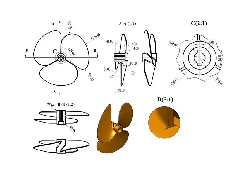
Based on the information provided by the customer2D Engineering Drawings (DWG/DXF/PDF)Based on this, parametric CAD modeling tools are used to convert plan views, dimensional annotations, section symbols, and tolerance information into precise 3D digital models. This process requires designers to possessAbility to Interpret Engineering Drawingsrespond in singingAbility to Reconstruct Spatial Geometry, to ensure that the model is consistent with the design intent of the drawings:
Drawing Analysis
Analyze the dimensional annotations, tolerance requirements, and surface roughness symbols in each of the three views (front view, top view, and side view) and the sectional view, and identify key reference planes and fit relationships.
Basic Modeling
In SolidWorks, UG, and NX, basic geometries are created using operations such as extrusion, rotation, sweeping, and lofting, with model parameters strictly driven by the dimensions specified in the drawings.
Add Detailed Features
Add detail features such as chamfers, fillets, draft angles, threaded holes, and ribs, and adjust the dimensional accuracy to ±0.02 mm according to the drawing annotations.
Assembly Verification
Perform interference checks and motion simulations on multi-part assemblies to verify clearance and range of motion, ensuring that the 3D models meet assembly and operational requirements.
3D Design of Casting Molds
He Xin CoverageHigh-pressure die-casting molds, low-pressure die-casting molds, gravity die-casting molds3D Design of Molds for Three Types of Casting Processes. Different casting processes have significant differences in terms of mold strength requirements, cooling design, parting line strategies, and venting layouts. The following sections cover these topics one by one, from design parameters to simulation methods:
Die Casting Mold Design
Low pressure casting mold design
Gravity casting mold design
A Comprehensive Comparison of Three Types of Casting Mold Design Parameters
| Design Parameters | Die-Casting Molds (HPDC) | Low-Pressure Casting (LPC) Molds | Gravity Die Casting (GDC) |
|---|---|---|---|
| Parting Line Accuracy | ±0.01 mm | ±0.03 mm | ±0.02 mm |
| Mold Materials | H13 / SKD61 Hot-Work Steel | H13 / QT500-7 | QT500-7 / HT250 |
| Mold life | 80,000–150,000 cycles | 30,000–50,000 cycles | 20,000–100,000 cycles |
| Cooling Method | Custom-Shaped Water Channels + Spot-Cooling Pipes | Water-Cooled/Air-Cooled, Zone-by-Zone Temperature Control | Natural cooling / Local forced air cooling |
| Exhaust Design | Parting Line Vent Grooves (0.08–0.15 mm) | Vent Plug (φ6–φ10 mm) | Parting Line + Sand Core Venting |
| Slider/Core Pull | Hydraulic Core Pull / Angled Guide Pins | Hydraulic Core Pull / Manual | Manual / Angled Guide Pins |
| Slope of Drawing | 1°–2° (internal) / 0.5°–1° (external) | 1.5°–3° | 2°–5° |
| Mold Development Cycle | 25–40 days | 20–30 days | 15–25 days |
| Number of Trial Mold Adjustments | ≤2 rounds | ≤2 rounds | ≤2 rounds |
| Mold Costs (Relative) | your (honorific) | center | Low to Medium |
| Adapted to Casting Wall Thickness | 1–6 mm | 3–15 mm | 4–30 mm |
| Typical Products | Automotive Sensor Housings, Electronic Heat Sinks | Aluminum Alloy Wheels, New Energy Motor Housings | Engine manifolds, hydraulic valve bodies |
CAE Mold Flow Simulation and Defect Prediction
He Xin incorporated this into the mold design phaseCAE Casting Simulation Analysis...uses numerical simulation to predict the filling behavior of molten metal in the mold cavity, the solidification process, and potential casting defects, thereby optimizing the design before the mold is machined. Core simulation capabilities cover the following areas:
Charging process simulation
Simulate the flow path, filling rate, and temperature distribution of molten metal within the mold cavity; predict defects such as entrapped gas, cold shuts, and underfill; and optimize the location of the internal gate and the cross-sectional area of the runner.
Analysis of the Solidification Process
Calculate the solidification sequence and solidification times for various sections of the casting; identify isolated liquid zones and hot spots; predict the likelihood of shrinkage porosity and shrinkage cavities; and optimize the layout of the risers and the cooling system.
Thermal Stress and Deformation
Analyze the distribution of thermal stresses and deformation trends in castings during solidification and cooling to predict the risk of hot cracking and dimensional deviations, and guide the design of mold counter-deformation compensation.
Mold Temperature Distribution
Simulate the temperature distribution and thermal equilibrium of the mold during continuous production to optimize the layout of the cooling channels and the parameters of the cooling medium, ensuring that the mold temperature remains stable within the process window (±10°C).
Common Technical Issues in 3D Design and Mold Development
Do you need reverse engineering or 3D mold modeling services?
Please send us your product drawings, photos of physical samples, or design specifications. Our engineering team will complete a technical evaluation within 24 hours and provide an estimated design timeline and a quote.
Send your drawings to get a design proposal →