


A Comprehensive Guide to Die-Casting Mold Acceptance Standards: 9 Key Acceptance Criteria, from Mold Materials to Finished Product Inspection
Excerpt:
Die-casting molds are the "gateway" to a product’s dimensional accuracy, surface quality, and production efficiency. A single oversight can result in an entire batch being scrapped. Based on actual factory acceptance checklists, this article comprehensively outlines nine major categories of mold acceptance criteria, along with finished product acceptance standards, mold price references, and maintenance schedules—all of which can be printed directly for on-site inspection.
Article Catalog[Hidden]
- 1. Why Does the Acceptance of Die-Casting Molds Determine the Upper Limit of Product Quality?
- 2. General Framework for the Acceptance of Die-Casting Molds
- 3. Mold Appearance Inspection: The First Step
- 4. Inspection of Mold Material and Hardness: The Key to Determining Mold Life
- 5. Mold Type, Cavities, and Production Method
- 7. Acceptance of the Pouring System
- 8. Cooling System Acceptance Testing
- 9. Slider System Acceptance
- 10. Acceptance of Molded Products: Final Verification of Mold Acceptance
- 11. Heat Treatment and Mold Maintenance Guidelines
- 12. Die-Casting Mold Price Guide
- 13. Summary Table of Acceptance Criteria for Die-Casting Molds
- 14. Frequently Asked Questions and Risk Disclosures
- 15. FAQ: Common Questions About Die-Casting Mold Acceptance
1. Why Does the Acceptance of Die-Casting Molds Determine the Upper Limit of Product Quality?
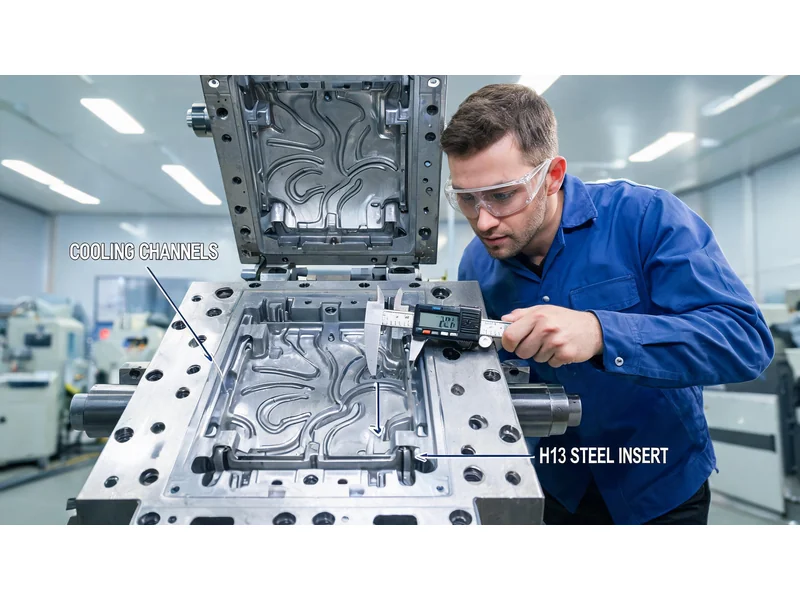
The material, hardness, cooling system, and ejection system design of die-casting molds directly determine whether the product can meet dimensional tolerance, surface quality, and airtightness requirements. Mold acceptance is not a mere formality—a 10-mm deviation in the spacing of cooling channels can lead to thermal fatigue cracking, and an ejector pin that is just 1 mm smaller in diameter may break and jam during production.
These acceptance standards are based on the actual acceptance processes at front-line die-casting plants and cover the entire acceptance process, from the die itself (9 major inspection categories) to the finished products (structure, appearance, and other aspects). Each standard includes quantifiable metrics that can be directly used for on-site check-off acceptance.
Core Philosophy:Mold Acceptance = The first line of defense for zero-defect delivery. The clearer the acceptance criteria, the fewer rework and claims there will be.
2. General Framework for the Acceptance of Die-Casting Molds
The acceptance process for die-casting molds consists of two main stages:
- Phase 1: Acceptance of the Mold Itself(9 Major Categories) — Appearance → Material/Hardness → Type/Cavity → Production Method → Ejection System → Gating System → Cooling System → Slider System
- Phase 2: Acceptance of Finished Products(3 Major Categories) — Product Structure → Product Appearance → Other Requirements
After acceptance, it is also necessary to follow the heat treatment and maintenance specifications to ensure stable operation of the mold throughout its entire service life. For more information, The Complete Process of Die-Casting Mold Manufacturing ... For more information, please refer to the special feature articles on this site.
3. Mold Appearance Inspection: The First Step
3.1 Dimensions and Weight
| Test Items | Receiving and Inspection Criteria |
|---|---|
| Mold Dimensions | Meets die-casting machine specifications and production safety requirements, and complies with the design drawings |
| Mold Weight | Suitable for the required die-casting machine specifications (if too large, clamping force will be insufficient; if too small, production capacity will be wasted) |
3.2 Mold Markings
- Mark the TOP surface of each formModel Number
- Additional holes must be drilled on the A/B panelPseudolaric acid
- Non-standard labeling → Difficulty in subsequent traceability
3.3 Mold Surface
The mold surface must be free of severe impacts, dents, deformation, and rust. Surface defects directly affect the product’s appearance and the smoothness of the demolding process.
4. Inspection of Mold Material and Hardness: The Key to Determining Mold Life
4.1 Die Core Material
| sports event | Standard Requirements | instructions |
|---|---|---|
| Mold Core Material | H13 Hot-Work Steel (2344 / 8407 / SKD61) | No weld repairs are permitted. |
| documentation | Proof of materials required + Heat treatment certificate | All are essential |
Important Warning:Repair weld areas are prone to thermal fatigue cracks. During acceptance inspections, a visual inspection must be conducted, along with non-destructive testing as necessary, to ensure that repair welds are not concealed.
4.2 Hardness Requirements
| Location | Hardness Range | instructions |
|---|---|---|
| Moren | HRC 46–52 | Certificates of material composition and heat treatment are required. |
| Slider | HRC 46–52 | Use heat-treatable steel for areas with adhesive; for areas without adhesive, use nitrided P20 or 45# steel. |
| Mold blank | LKM Standards / Other Standards | Must operate smoothly at high temperatures |
4.3 Mold Life Benchmarks
| Alloy Type | Mold life |
|---|---|
| aluminum | 100,000–200,000 cycles |
| zinc alloy | 300,000 cycles |
If mold life falls short of specifications, there is a problem with the material or heat treatment. For a comparison of mold life and performance across different casting processes, please refer to Guide to Selecting Casting Processes.
5. Mold Type, Cavities, and Production Method
5.1 Mold Types
| Type | Receiving and Inspection Criteria |
|---|---|
| Center Nozzle | Meet product quality requirements + comply with die-casting machine specifications |
| Eccentric Nozzle | Must meet the required die-casting machine specifications |
5.2 Selecting the Number of Cavities
| Number of cavities | Basis for Selection |
|---|---|
| 1 Acupoint | Customer Requirements / Complex Product Design |
| 2 Acupoints | Balance Between Supply and Demand |
| 4 Acupoints | High-volume, simple-structure products |
| Other | Customization for Special Needs |
5.3 Production Methods
| way (of life) | Requirements |
|---|---|
| Automatic | The product must release automatically, not stick to the mold, and be easy for a robotic arm to grasp. |
| Semi-automatic | Can proceed with automated production |
| Manual | Use when automated production is not possible |
6.1 Thimble Specifications
| Test Items | Receiving and Inspection Criteria |
|---|---|
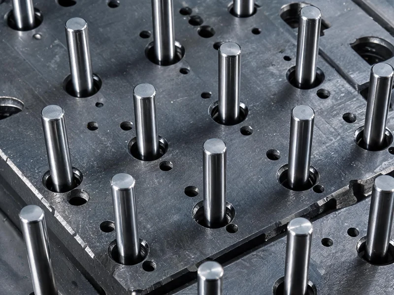
| material (that sth is made of) | Full-Hard Pin for Hot-Work Steel |
| Minimum Diameter | Not less than Φ4 mm |
| Load Requirements | Balanced force distribution during ejection, smooth operation |
| Top Trips | The highest point of the product as it is ejected from the mold insert must be at least 6 mm. |
| Sitong Top-Out | Do not perform a top-out move on the S-Tong |
6.2 Returning the Ejection System to Its Original Position
- Standard Method:Return the retraction mechanism to its original position
- Springs can be used for small/simple molds, provided they meet the mold's service life requirements.
6.3 Thimble Clearance
| Thimble Diameter | Fitting Clearance |
|---|---|
| > Φ10mm | 0.04 mm |
| ≤ Φ8 mm | 0.02 mm |
7. Acceptance of the Pouring System
| Test Items | Receiving and Inspection Criteria |
|---|---|
| Side-Entry Injection | The gate location facilitates filling and trimming |
| The Bottom of the Flow Channel and the Corner | Rounded corners and a polished finish are required; sharp corners are not allowed. |
| Gate and Slag Ladle Length | No less than 2 mm, with appropriate depth |
| Gate Sleeve Dimensions | Complies with the specifications for die-casting machine pistons; if the trial-molding machine is not compatible with the production machine, a separate gate sleeve must be fabricated for trial molding. |
| Eccentric Nozzle | Must comply with die-casting machine specifications |
| Gate Cross-Sectional Area | The right size affects filling speed and porosity. |
| flow cone | Must be cooled separately |
8. Cooling System Acceptance Testing
| Test Items | Receiving and Inspection Criteria |
|---|---|
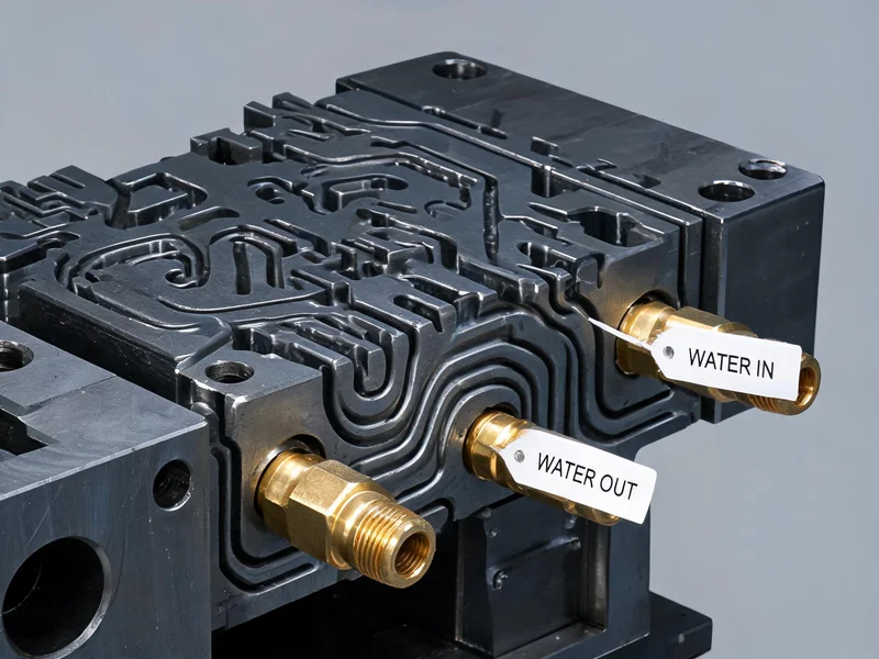
| Cooling Requirements | The cooling channels provide sufficient cooling for the product; the gate sleeves and runner cones must be cooled separately. |
| Channel Spacing | The spacing between the channels is approximately 40 mm |
| Distance from the cavity | Not less than 20 mm |
| Distance from the thimble screw | 10mm |
| Connection Methods | The nozzle is connected directly to the mold core,Waterproof seal not available |
| Waterway Patency | The cooling water channels must be unobstructed and free of leaks. |
| Import and Export Markings | Import and export points must be clearly marked |
| Tooth Profile | Unless otherwise specified, use PT teeth. |
Key Metrics:A 40mm spacing between channels, a distance of ≥20mm from the cavity, and a distance of 10mm from the ejector screw—these three figures are the "hard limits" for the acceptance of the cooling system.
9. Slider System Acceptance
9.1 Effects of Line-Position Movements
| Test Items | Receiving and Inspection Criteria |
|---|---|
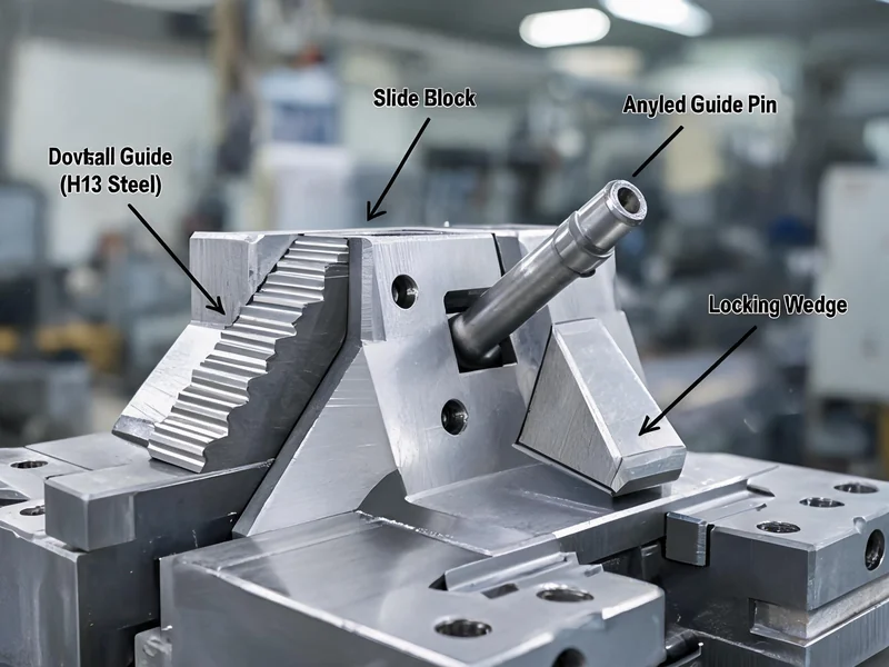
| Smoothness of Sliding | Smooth glide |
| Travel > 40 mm | The motion must be controlled by a hydraulic cylinder and a microswitch. |
| Diameter of the inclined guide post | Not less than Φ20 mm |
| Inner Slider | Avoid machining the inner slider as much as possible |
| Matching Segment Length | The section where the slide engages with the clamping plate shall be no less than 2/3 of the slide's length. |
9.2 Steel for Sliders
| Conditions | Steel Material Requirements |
|---|---|
| Glue application area | Hot-rolled steel |
| No-glue position | Nitriding of P20 or 45# Steel |
9.3 Feed Trough and Hole Locations
- A material chute must be installed beneath the conveyor.
- Small holes are not ejected separately—they move to the next station along with the part, and the holes are machined afterward.
- Locating holes must be provided on the mold.
10. Acceptance of Molded Products: Final Verification of Mold Acceptance
10.1 Product Structure
| Acceptance Criteria | (an official) standard |
|---|---|
| Dimensions (FAI/CPK) | After polishing: FAI passed & CPK > 1.67 |
| Post-Processing Structure | Post-processing features not to be machined on the mold must be specified prior to mold opening. |
| Product Edges and Corners | Sharp corners are not allowed; R1 for protrusions, R2 for recesses |
10.2 Product Appearance
| Defect type | Receiving and Inspection Criteria |
|---|---|
| Cold-formed patterns or corrugations | Meets the customer's acceptance criteria or, after polishing, does not have |
| Edge-Trimmed Pieces | Easy to sand and machine |
| Crack | Not allowed |
| Pores or Shrinkage Holes | Not allowed |
| Peeling | Not allowed; after polishing, there are none, and the strength requirements are met. |
| Carbon Deposits | This is not permitted; the mold must undergo regular decarbonization. |
| mold sticking | Not allowed |
| Material Shortage | Not allowed |
10.3 Other Product Requirements
| sports event | Requirements |
|---|---|
| Demolding of Slender Holes | For slender holes with a diameter < Φ2.5 mm on a mold that will not be machined on-site but will undergo subsequent machining, SQCC must first approve the design, and positioning holes must be machined into the mold. |
| Parting line | Avoid dents as much as possible; do not chamfer the edges of frames or holes; ensure a 0.1 mm gap between the A and B panels. |
| Exhaust Slag Liner | There must be a sufficient number of slag pots; there must also be a slag pot at the end of the runner; when venting, avoid direct venting into the channel to prevent injury. |
For finished product inspection, we recommend referring to Inspection Procedures and Acceptance Criteria in Aluminum Casting Production , to ensure that the acceptance results are objective and reliable.
11. Heat Treatment and Mold Maintenance Guidelines
11.1 Tempering and Heat Treatment
| working procedure | Requirements |
|---|---|
| Stress-Relief Tempering | After rough machining the mold and before finishing, the following must be performed: |
| Quenching and Tempering | The heat treatment process must be strictly controlled, and the following steps must be performed: 3. Second Tempering Treatment |
11.2 Mold Maintenance Schedule
| Maintenance Milestones | Maintenance Procedures |
|---|---|
| Mass production of the new mold begins after 6,000 molds have been produced | Initial Stress-Relief Tempering |
| For every 10,000 molds produced in a batch | Stress-Relief Tempering |
| Approximately every six months of production | One mold disassembly and cleaning |
| Periodically | Carbon Deposits Removal Treatment |
12. Die-Casting Mold Price Guide
The price of die-casting molds is influenced by various factors, including alloy type, complexity, number of cavities, steel grade, and number of sliders. The following price references are based on data from the Chinese market for 2025–2026 and are provided for use in evaluating procurement budgets.
12.1 Classification by Alloy Type and Complexity
| Mould Type | Level of complexity | Price Range (USD) | Price Range (RMB) | Lifetime (die times) |
|---|---|---|---|---|
| Zinc Alloy Die-Casting Molds | Simple Single-Chamber | $3,000~15,000 | ¥22,000–108,000 | 500,000–1,500,000 |
| Zinc Alloy Die-Casting Molds | Medium/Multi-chamber | $3,000~15,000+ | ¥22,000–108,000+ | 500,000–1,500,000 |
| Aluminum Alloy Die-Casting Molds | Simple Single-Chamber | $5,000~20,000 | ¥36,000–144,000 | 20,000–30,000 |
| Aluminum Alloy Die-Casting Molds | Moderately complex | $25,000~40,000 | ¥180,000–288,000 | 50,000–80,000 |
| Aluminum Alloy Die-Casting Molds | Complex, multi-chambered | $50,000~80,000+ | ¥36,000–576,000+ | 100,000+ |
| Aluminum Alloy Automotive Parts (Single-Chamber) | Moderately complex | $25,000~60,000 | ¥180,000–432,000 | 80,000–150,000 |
| Aluminum Alloy Automotive Parts (4–8 Cavities) | Complex, multi-chambered | $80,000~200,000 | ¥57.6–1.44 million | 80,000–150,000 |
12.2 Price Multiplier Based on the Number of Cavities
| Number of cavities | Price Multiple | instructions |
|---|---|---|
| 1 Acupoint | 1x | standard of reference |
| 2 Acupoints | 1.4–1.6x | Shared components, not double |
| 4 Acupoints | 2.5–3x | Because of shared components, it is not 4 times |
| 8 Acupoints | Higher | Sliders + Cooling + Balanced Flow Channels Increase Costs |
12.3 Breakdown of Mold Costs
| Cost Items | Percentage of total mold cost | instructions |
|---|---|---|
| Mold Design Fees | 2%~3% | Large models: approximately 2%; small models: approximately 2.5–3% |
| Processing Fees | ≤20% | CNC, EDM, heat treatment, polishing, etc. |
| Testing Fees | 1%~2% | Inspection of Critical Dimensions, Male Core, and Mold Core |
| Tooling Costs (≤800T) | 1%~1.5% | Molds under 800 metric tons |
| Mold Testing Fee (>800T) | 2% | Molds rated at 800 metric tons or more |
| After-Sales Maintenance Fees (≤800T) | 1%~1.5% | Debugging, Performance Tuning, Warranty Service |
| After-Sales Maintenance Fees (>800T) | 2% | Large Molds |
| Shipping Costs | 0.5%~1.5% | Depending on the customer's location |
| Taxes and Fees | Approx. 9% | After deducting the cost of materials, the company will cover the remaining amount. |
12.4 Additional Factors Affecting Prices
| Factors | Price Impact |
|---|---|
| Steel Grade: ESR H13 vs. Standard H13 | ESR H13 is 20%–40% more expensive per kilogram |
| Slider/Sloped Roof | Increase mold cost by 15%–25% + 1–2 weeks of trial molding time |
| Mirror Polishing | Additional costs for surface treatment and polishing |
| Texturing/Etching | Additional Texture Processing Fees |
| Tight Tolerance Accuracy | Increase in processing and inspection costs |
Quick Price Calculator:Aluminum alloy die-casting molds (medium complexity, single cavity) cost approximately 180,000–288,000 yuan; 4-cavity automotive part molds cost approximately 576,000–1,440,000 yuan. With a mold life of 80,000–150,000 cycles, the amortized cost per part is approximately 0.36–3.6 yuan.
For information on strategies for balancing minimum order quantities and mold costs for aluminum castings, please refer to Frequently Asked Questions and Lead Times for Die-Casting Factories . For mold investment during the prototype phase, we recommend referring to A Comprehensive Analysis of Aluminum Die-Casting Mold Design .
13. Summary Table of Acceptance Criteria for Die-Casting Molds
The following summary table consolidates all 9 major categories of mold acceptance criteria plus finished product acceptance criteria and can be printed directly for on-site acceptance inspections.
| No. | Acceptance Categories | Test Items | Receiving and Inspection Criteria | Passed |
|---|---|---|---|---|
| 一 | Mold Appearance | Dimensions | Compliant with die-casting machine specifications and design drawings | ☐ |
| weights | Suitable for the required die-casting machine specifications | ☐ | ||
| Mold Markings | Mark each form with a form number; for A/B panels, also include the product name. | ☐ | ||
| 二 | Mold Material & Hardness | Mold Core Material | H13-class hot-work steel (2344/8407/SKD61), no weld repairs | ☐ |
| Die Face Hardness | HRC 46–52, with heat treatment certificate | ☐ | ||
| Slider Hardness | HRC 46–52 | ☐ | ||
| Mold blank | LKM standard or other standards; smooth operation at high temperatures | ☐ | ||
| Mold life | Aluminum: 100,000–200,000 molds / Zinc: 300,000 molds | ☐ | ||
| 三 | Mold Type | Center Nozzle | Meeting Quality Requirements + Die-Casting Machine Specifications | ☐ |
| Eccentric Nozzle | Meets die-casting machine specifications | ☐ | ||
| 四 | Mold Cavity | 1 Acupoint | As requested by the customer | ☐ |
| 2 Acupoints | Production volume meets production needs | ☐ | ||
| 4 Acupoints | The complexity of the product structure allows for this | ☐ | ||
| Other | Special Needs | ☐ | ||
| 五 | Production Methods | Automatic | Automatic demolding, non-stick, and easy to handle with a robotic arm | ☐ |
| Semi-automatic | Capable of automated production | ☐ | ||
| Manual | Use when there are no automatic conditions | ☐ | ||
| 六 | Ejector system | Thimble | Hot-work steel, fully hardened, ≥Φ4 mm, ejection ≥6 mm | ☐ |
| Return to Position | Return mechanism resets (spring used only in small models) | ☐ | ||
| Gap | >Φ10: 0.04 mm / ≤Φ8: 0.02 mm | ☐ | ||
| 七 | Gating System | Side-Entry Injection | Easy to fill and remove | ☐ |
| Flow Channel | Rounded edges + polished, no sharp corners | ☐ | ||
| Spout/Slag Ladle | Length ≥ 2 mm | ☐ | ||
| Gate Sleeve | Meets the specifications for die-casting machine pistons | ☐ | ||
| Gate Cross-Sectional Area | Just the right size | ☐ | ||
| 八 | cooling system | Cooling Requirements | Sufficient cooling channels; separate cooling for the gate sleeve and diverter cone | ☐ |
| Channel Spacing | Spacing of approximately 40 mm; distance from the cavity ≥ 20 mm | ☐ | ||
| Connection Methods | The nozzle connects directly to the mold insert; no O-ring is needed. | ☐ | ||
| Flowability | The waterways are clear and free of leaks, and the inlets and outlets are marked. | ☐ | ||
| 九 | Slider System | Movements and Positions | Smooth sliding; use a hydraulic cylinder for distances greater than 40 mm | ☐ |
| Angled Guide Pillar | ≥Φ20 mm | ☐ | ||
| Coordinating Section | ≥ 2/3 of the line length | ☐ | ||
| Steel | Hot-work steel with adhesive joints / P20 nitriding without adhesive joints | ☐ | ||
| 十 | Product Structure | Dimensions | FAI passed & CPK > 1.67 | ☐ |
| Post-Processing Structure | You'll know before tooling begins | ☐ | ||
| Edges and corners | R1 is convex, R2 is concave, and there are no acute angles | ☐ | ||
| Eleven | Product Appearance | Cold-Formed Patterns/Corrugations | Meets acceptance criteria or, after polishing, shows no | ☐ |
| Rough-cut pieces | Easy to sand | ☐ | ||
| Crack | Not allowed | ☐ | ||
| Pores/Shrinkage Holes | Not allowed | ☐ | ||
| Peeling | Not allowed | ☐ | ||
| Carbon Deposits | Not allowed | ☐ | ||
| mold sticking | Not allowed | ☐ | ||
| Material Shortage | Not allowed | ☐ | ||
| Twelve | (sth. or sb) else | Parting line | No dents; 0.1 mm gap between the A and B panels | ☐ |
| Exhaust Slag Liner | Enough, with a bag of dregs at the end | ☐ | ||
| Slotted Hole | <Φ2.5mm后加工,须定位孔 | ☐ | ||
| Thirteen | Heat Treatment & Maintenance | Tempering | Stress relief after rough machining, followed by three cycles of quenching and tempering | ☐ |
| Maintenance Schedule | First maintenance at 6,000 cycles / Tempering at 10,000 cycles / Cleaning every six months | ☐ |
Do you need die-casting mold design and manufacturing services?
Ningbo Hexin Molding Co., Ltd. — With 16 years of experience in aluminum alloy casting, we provide end-to-end die-casting solutions, from mold design and manufacturing to final acceptance.
Contact Us Now →14. Frequently Asked Questions and Risk Disclosures
Risk 1: Substandard Materials Used in Place of Genuine Ones
Passing off P20 as H13 → Double verification via hardness testing and material certification. The thermal fatigue performance of P20 is far inferior to that of H13, and mold life may be reduced by 50% or more.
Risk 2: Insufficient cooling
Excessive spacing between cooling channels or excessive proximity to the cavity → thermal fatigue cracking. During acceptance inspection, it is essential to strictly adhere to the two mandatory requirements: a 40-mm spacing and a 20-mm distance from the cavity.
Risk 3: Insufficient engagement length of the slider
The clearance between the slide and the pressure plate is < 2/3 → Loose slide, flash. This directly affects product dimensions and appearance.
Risk 4: The thimble is too thin
Diameter < Φ4 mm → Prone to breakage and jamming. Production downtime + high maintenance costs.
Risk 5: Concealment of Repair Welds
High risk of thermal fatigue cracks in the repair weld area → Visual and non-destructive testing. Repair welds are the leading cause of premature mold failure.
For the complete process of selecting and purchasing automotive aluminum alloy castings, please refer to Die-Casting Services and Selection of Aluminum Alloy Castings . To learn more about the applications of the low-pressure casting process, please read Applications and Typical Uses of Low-Pressure Casting .
15. FAQ: Common Questions About Die-Casting Mold Acceptance
Q1: What is the required hardness for die inserts in die-casting molds?
The hardness requirements for die inserts in die-casting molds are as follows: HRC 46–52, H13-class hot-work steel (such as 2344, 8407, or SKD61) must be used, and certificates of material and heat treatment must be provided.
Q2: What type of steel is used for die-casting molds? Can P20 be used?
The mold core standard requires the use of H13-type heat-resistant steel(2344/8407/SKD61). When the slider has a rubber contact area, hot-work steel must be used; when there is no rubber contact area, P20 or 45# steel treated with nitriding may be used. P20 is not recommended for die inserts.
Q3: What is the typical service life of a die-casting mold—in terms of tens of thousands of castings?
The service life of an aluminum alloy die-casting mold is 100,000–200,000 cycles, The service life of zinc alloy die-casting molds can reach 300,000 cycles. Mold life is closely related to the material, heat treatment, and maintenance schedule.
Q4: What are the acceptance criteria for porosity in die-cast products?
Die-Cast ProductsNo air pockets or shrinkage cavities are allowed., and there must be no cracks, peeling, carbon buildup, mold sticking, or material shortages. Cold marks or ripples must comply with the customer’s acceptance criteria or be eliminated after polishing.
Q5: What is the maintenance interval for die-casting molds?
Mass Production of New Molds After 6,000 moldsAn initial stress-relief tempering treatment must be performed; thereafter,Per 10,000 moldsA stress-relief tempering treatment must be performed,Every six monthsThe left and right dies should be disassembled and cleaned once, and carbon deposits should be removed periodically.
Q6: What supporting documents are required for the acceptance of die-casting molds?
Requirements for the acceptance of die-casting molds:documentation(H13 Heat-Resistant Steel Material Report),Heat Treatment Certificate(HRC 46–52 Hardness Report),Mold Design Drawings,Dimension Inspection Record Formand other documents.