Differences between milling and planing machines
Article Catalog[Hidden]
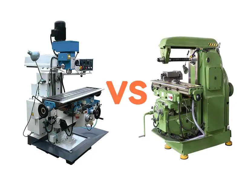
In the grand picture of machine building, metal cutting processing occupies a central position. As a key means of achieving precise shapes and sizes of parts, various machine tools have come into being, and together they have driven the progress of industrial civilization. Among them.machining centerrespond in singingplaning machineAs two types of machine tools with a long history and a strong foundation, they played an indelible role in shaping the early stages of the foundation of modern industry. Although they belong to the same removal of material processing category, but its core working principle, applicable processing objects and embodied process characteristics, but there are essential differences.
Milling machine, with its rotating multi-flute cutter (milling cutter) as the main feature, can efficiently machine flat surfaces, grooves, gear tooth shapes, helical surfaces, and a variety of complex curved surface contours through the high-speed rotation of the cutter and the multi-directional feeding motion of the workpiece. Its machining process is relatively continuous and highly flexible, especially good at accomplishing the task of machining parts with complex shapes and high precision requirements.
Planers, on the other hand, are known for their unique linear reciprocating motion. The tool (planer) or workpiece carries out a linear reciprocating cutting motion (main motion) in the horizontal direction, together with intermittent feed motion (usually perpendicular to the direction of the main motion), mainly used for machining horizontal surfaces, vertical surfaces, inclined surfaces, and all kinds of linear grooves. The planing process is characterized by the "one-tool-shaping" feature, which often shows its unique advantages and accuracy potential when machining large planar surfaces or long straight guideways.
Understanding the fundamental difference between milling machines and planers is not only a retrospective look at the evolution of machining technology, but also the key to mastering the basic principles of metal cutting. This difference profoundly affects their machining efficiency, applicability scenarios, economy, and development trajectory in the wave of automation. With the rise of CNC technology and composite machining centers, although the direct application of the two in high-end manufacturing has evolved, their core principles are still inherited and developed, and their historical status and unique value in specific application scenarios are still worthy of in-depth exploration.
The purpose of this report/article is to systematically analyze the role of milling and planing machines in thePrinciple of operation, form of motion, machining capacity, process characteristics, scope of application and advantages and disadvantagesThe core differences in these aspects are intended to provide a clear cognitive foundation for understanding the essence of traditional machining methods, rationally selecting machining equipment, and recognizing the evolution of modern manufacturing technology. The following sections will discuss each of these in detail.
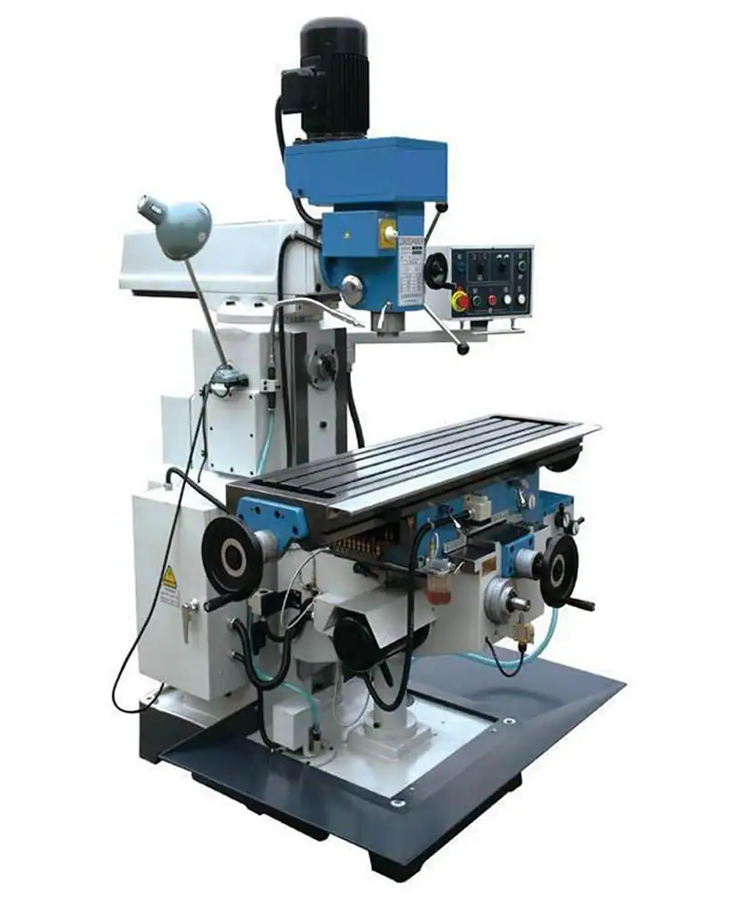
machining center
1. Overview
Milling Machine: Milling Machine
A versatile machine tool, on which flat surfaces (horizontal and vertical), grooves (keyways, T-slots, dovetail grooves, etc.), gear parts (gears, spline shafts, sprockets), helical surfaces (threads, helical grooves), and curved surfaces can be machined. In addition, it can also be used for the surface of rotating bodies, internal hole processing and cut-off work. Milling machine in the work, the workpiece mounted on the table or indexing head and other accessories, milling cutter rotation as the main movement, supplemented by the table or the milling head of the feed movement, the workpiece can be obtained the required processing surface. Because it is a multi-tool intermittent cutting, thus the productivity of the milling machine is high.
Planer:
It is mainly used for machining various flat surfaces (such as horizontal, vertical and oblique surfaces and various grooves, such as T-slot, dovetail groove, V-groove, etc.) and straight molding surfaces. If equipped with profiling device, it can also process space surface, such as turbine impeller, spiral groove and so on. This type of machine tool structure is simple, the return trip does not cut, so the productivity is low, generally used for single-piece small batch production.
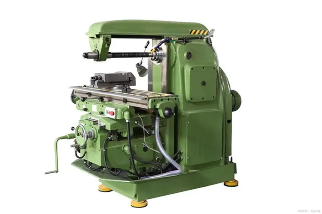
planing machine
2. Consider the following aspects:
- 1: from the working principle of the machine tool considerations, planer table and tool to go cross-shaped linear reciprocating motion, milling machine table and tool vertical, at the same time with X, Y, Z axis, do rotary motion.
- 2: From the processing of like considerations, planer generally to add in the face of the main, and a single clamping method. While the milling machine can be processed plane (horizontal, vertical), groove (keyway, T-shaped groove, dovetail groove, etc.), gear parts (gears, spline shafts, sprocket wheel, spiral surface (thread, spiral groove) and a variety of curved surfaces. In addition, it can also be used for machining the surface of rotating bodies, internal holes, and cutting off work, etc. The clamping method is much more complicated than that of the planer.
- 3: In terms of accuracy, milling machines are generally more accurate than planers.
- 4: from the required processing tool above considerations, planer tools are generally sharp steel hand-ground and become, the processing surface is generally flat. And milling machine with tools for the processed shaped milling cutter.
- 5: from the efficiency considerations, due to the planer by the processing object, clamping, tooling, low efficiency, can only be used for roughing or single piece of parts that do not require high processing, so the planer slowly in the machining industry is not used. The milling machine clamping flexible, processing like a wide range of high precision, so high efficiency, generally more popular in the machining industry.
- 6: In terms of processing costs, planers are lower than milling machines.
3. Their main differences in actual production:
Planer: generally used for planing plane, the advantage lies in the straightness and flatness than the milling machine is good, so the long type of workpiece plane or planer processing is better, and loading general vise can be, such as key. With the support of some tooling, you can process a lot of molded surfaces, in general general-purpose machine tools, surfaces are still processed on the planer. Even planers can machine gears.
Milling machine: high machining efficiency, can be indexed, in the processing of large surface area has the advantage, and the complexity of the tool, there is a great advantage in machining.
The main drive of this machine tool adopts DC motor, the table running speed is stepless speed regulation, its wide speed range can meet the various speed requirements of planing, milling and grinding, and it can process various materials such as horizontal, vertical, inclined surfaces, T-slots, combined guide surfaces and racks.
Advanced ultra-audio quenching process makes the service life of the machine tool longer. Split feeding system of column and beam makes the operation more convenient and flexible. Independent oil pump lubrication system makes various working conditions smoother. Thermal aging plus vibration aging makes the machine tool more stable and durable. Planing, milling, grinding three in one, one machine multi-purpose, make processing more flexible, is the most ideal machining equipment for machining, machine shop. Execution standard: "Heavy-duty gantry planer and milling machine precision standard" JB/T10226-2001 standard
Introduction to heavy duty gantry planer and milling grinder
- Crossbeam locking is motorized, depending on machine characteristics.
- Heavy duty gantry planer milling grinder machine tool guideway table lubrication Pilot realizes adjustable semi-static oil float lubrication, low friction, saving running power 30%-50%, long lasting guideway precision without friction, guaranteeing machine tool precision.
3. The main drive of the machine tool is the international advanced European DC speed control technology, the horizontal beam feeding and side tool box feeding are the most advanced IMS-GCT AC servo control, which can intermittently and continuously feed without adjusting the amount of feed, and the positioning accuracy is within 0.10mm (mechanical error is not counted), so that the processing of planing, milling, and grinding can realize the technological upgrading, which is the leading one in the industry.
1, heavy gantry planer and milling grinder machine tool main components: bed, table, left and right columns, beams, gantry top, connecting beams are resin sand molding, high-quality high alloy wear-resistant cast iron casting, through the sand pit annealing → vibration aging → hot furnace annealing → vibration aging → rough machining → vibration aging → hot furnace annealing → vibration aging → finish machining, completely eliminate negative stress in the machine parts, and keep the performance of the machine parts stable.
2、The lifting and positioning of the beam is mechanical locking or hydraulic locking, accurate positioning.
3、Transverse feed of crossbeam vertical cutter holder (vertical milling head) and vertical feed of side cutter holder (side milling head) gantry planer milling are AC servo control, intermittent and continuous stepless feed.
4、Heavy duty gantry planer milling grinder machine guideway surface is hardened by ultra-audio quenching or point-contact hardening treatment, and finely ground.
5、High wear-resistant guide belt vice is bonded on the surface of table guideway.
Basic knowledge of gantry planer milling machine
Gantry planer and milling is useful for double column crossbeam lifting gantry structure, the machine tool consists of bed, table, gantry frame, crossbeam, slide seat, spindle box, ram, milling head and electrical and other main parts.
The table moves longitudinally along the rails of the bed (X-axis), the slide moves transversely along the rails of the crossbeam (Y-axis), the crossbeam moves vertically along the vertical rails of the right and left columns (W-axis), and the square ram carries the main spindle box vertically in the slide (Z-axis). The main drive is transmitted from the main drive shaft in the square ram to each milling head through the spline vice.
Gantry planer milling adopts low-noise linear rolling guide with cage, which can withstand loads in several directions, with high rigidity, high load carrying capacity, high dynamic rigidity and high motion accuracy. The motor control coefficient is extremely small and convenient for lubrication. Spindle box balancing and beam balancing adopt hydraulic balancing.
The gantry planer milling machine is equipped with full digital numerical control system, DC spindle motor for main drive, AC servo motor for each axis drive, with corresponding speed regulating device and driving device.
According to the user's processing needs can be equipped with a variety of quick-change attachment head, in the workpiece under the one-time loading can be completed inside and outside the five-face boring, milling, drilling, cutting holes and other processing procedures. CNC control system can realize any three-axis linkage, realize contour milling. The machine beam and ram adopt high-precision ball screws, which are frictionless, with high transmission efficiency, large bearing capacity in the direction of movement, and maintain high-precision transmission at high rotational speeds, with long service life and durability. Gantry planer milling machine is a newly developed product of our company, absorbing the structural characteristics of advanced machine tools at home and abroad, adopting advanced technology to manufacture, the machine tool has good performance, reliable structure, simple operation, easy maintenance, widely used in the machining industry for milling of heavy ferrous, non-ferrous metals in plane, inclined and concave-convex surfaces, with a good performance-price ratio.
Main structural characteristics of machine tools
The bed, table, column, crossbeam and other basic parts are made of resin sand molding, high-strength HT300 high-quality cast iron with aging treatment, with reasonable design structure, good casting and machining processability, high rigidity, good deflection resistance and excellent precision stability. The gantry frame consists of left and right columns, cross beams and bed, etc. The lower end of the columns is firmly connected with the bed, and the upper end of the columns is firmly connected with the cross beams to form a high rigidity gantry frame structure.
Gantry planer milling knowledge in detail
Gantry planer milling is a general-purpose large machine tool, widely used in the field of plane processing, most of the current machine tool equipment bed processing to use gantry planer milling. Early gantry planer circuit design mainly adopts the traditional generator set + DC motor form. Due to this circuit efficiency is extremely low, the noise is also very large. With the development of electronic technology, this type of design has been eliminated, replaced by switched reluctance speed control system and DC speed control system.
1. Function Introduction
The controller has PLC function, thus realizing the integrated control of gantry planer milling machine. One set of servo control system is the whole gantry planer milling system, which brings great convenience to customers.
1、Bench movement: control the bench motor positive and negative operation, realize the point, automatic positive and negative movement.
2, feed knife control: according to the mechanical needs of the mechanical box can be controlled to feed the knife, delayed feed knife, and servo feed knife mechanism.
3, beam lifting control: control the lifting and lowering of the beam, including the lifting and lowering action of the beam, the relaxation and locking action of the beam, as well as the anti-lifting action of the beam after descending.
2、Performance Advantage
1、Energy saving and noise reduction
Adopting time asynchronous servo system can effectively save power and reduce noise. After adopting a certain system, the efficiency of the motor can be increased to more than 90%, and the noise is far less than the DC system as well as the switched reluctance system.
2、Strong overload capacity
The system can realize 2 times overload below the rated speed of the motor, which makes the cutting force bigger and the operation faster and smoother. Precise control makes it possible to change direction without shock.
3. Increased functionality and improved performance
The speed control ratio of the system is more than 1:5000, so that the integration of planing, milling and grinding can be realized under the premise of simplifying the mechanical structure design, and the simplification of the machinery can also effectively avoid the phenomenon of mechanical crawling.
Single arm planer performance characteristics
1、Beam and vertical milling head with fully automatic mechanical compression, hydraulic relaxation function. Higher degree of automation.
2. The milling head is equipped with a built-in flywheel, which makes the cutting smoother.
3、Movement of vertical milling head on the crossbeam, up and down movement of side milling head on the column, and worktable work feed are all adopting frequency conversion stepless speed regulation, which is conducive to the selection of reasonable cutting parameters, and is more convenient to use.
4、Working table adopts new technology of wear-resistant sticking plastic guide rail, which can reduce the wear and tear of bed guide rail.
5、Working table adopts worm gears and worm gears, the movement is smoother (below 6M adopts silk rod drive).
6, the table worm worm with independent oil groove immersion oil lubrication, table guide rail with independent oil tank special lubrication pump lubrication (can ensure the cleanliness of the guide rail lubricant), milling head with independent plunger pump lubrication, beam column guide and beam column screw with manual pump lubrication, the whole machine has a good abrasion-reducing lubrication performance.
7, the bed and beam guide rail adopts super audio quenching heat treatment, wear-resistant performance is greatly improved.
8、The beam guideway adopts anti-deformation grinding process, which can eliminate the deformation generated by the milling head moving on the beam.
Single arm planer operating procedures:
Carefully implement the following general provisions regarding gantry planers:
1, the installation of the workpiece should make the table force uniform, to avoid uneven force resulting in deformation of the table.
2、After the workpiece is loaded, the table must be moved at a low speed to check that there is no collision and no problem with the stroke and direction change before working.
3. Table operation and crossbeam raising and lowering are not allowed at the same time. After each descent of the crossbeam, it should rise a little more to eliminate the clearance of the screw nut.
4, table travel, generally shall not be less than one-third of the full stroke, the use of the longest stroke, the speed should be lower, so that the reverse overrun stroke is not greater than 100 mm is appropriate.
5、When the table is running, it is absolutely forbidden to stand on the table surface to operate or do other adjustment work.
Carefully implement the following special bead provisions for gantry planers:
(1) Single-arm planer:
1、When the width of the processed workpiece exceeds the width of the worktable, the center of gravity of the workpiece shall not be offset to the center of the worktable by more than 1/4 of the width of the worktable.
2、After work, the table should be stopped in the middle position of the machine, the side tool holder of the crossbeam is lowered to the lowest position, and the vertical tool holder is placed at the end of the stand.
(2) Gantry planer:
After work, the table should be stopped at the center of the machine, the crossbeam and side tool holders should be lowered to the lowest position, and the two vertical tool holders should be placed against each side of the column.